Questions, amendments and additions are welcome. Mail to rotoplan@narod.ru
(Almost) all pictures are clickable.
Sverchkov's Samoljot, St-Peterburg, 1909.
This craft was called "Samoljot", but it had also another name — "wheel orthopter". Its scheme came near to cyclogiro, but it's difficult to classify it precisely. It had three flat surfaces and a rudder; rear edge of one of surfaces could be bent, replacing the action of an elevator. Lift and thrust had to be created by paddle wheels consisting of 12 blades, established in pairs under a 120° angle. The blades of a concave shape were changing an angle of incidence by the means of eccentrics and springs. In a bottom of the craft 10 hp Bushe engine was arranged, from which the belt transmission was running. The three-wheel undercarriage was made droppable and was intended for takeoff only. Fabric-covered framework was made of thin-wall steel tubes and bamboo trunks with steel strings inside. Empty weight was about 200 kg. "Samoljot" was constructed by the military engineer E.P.Sverchkov with the grants of the Main Engineering Agency in St.Petersburg in 1909, was demonstrated at the Newest Inventions Exhibition and won a medal. But the tests have passed unsuccessfully: it not only has not come off ground, but even has not moved from a place.
The famous Russian inventor and scientist, engineer-electrician A.N.Lodygin in 1914 has addressed to Russian government with the project of the cyclogiro-like aircraft, which scheme was similar to Sverchkov's "Samoljot". The project was not carried out.
It is interesting to note, that in 1935 the famous German designer A.Rohrbach has acted with the rather similar cyclogiro project, which was published in aviation magazines.
"History of aircraft construction in the USSR (till 1938)" by V.B.Shavrov
A.K.Medvedev has addressed to Military Department with the offer to carry out "paddle wheel". His wheel was consisted of a steel box with four attached blades. The box received rotary movement from the engine and oscillatory movement - from the air pump. The change of an axis movement was made on 1/8 move of a box, and 3/8 move the axis should be in rest, only rotating together with a box. Such a paddle wheel, on an idea of the inventor, had to replace the action of a propeller. The department of the inventions of Military-Industrial Committee, having considered this project, has recognized it "low-practical" and has informed Medvedev, that does not assume to use his offer.
"History of aerostation and aviation in Russia (1914-1917)" by P.D.Duz
The sole ornithopter project, which had receive support from the Military Aviation Department during war, was the A.G.Mikhailov's craft. At the end of 1916, Mikhailov has addressed to the chief of Main Military Engineering Department with the request of support in construction of the craft, invented by him. For consideration of the project the commission was created, which included the constant members of Military Aviation Department Technical Committee profs. G.A.Bothesat and A.A.Lebedev. The inventor has presented to commission the drawings and description, from which followed, that he offers the ornithopter-like craft. Paddle wheels were carried out from a steel tape, with corner profiles riveted to it. Profiles could change an angle of an inclination with the help of pneumatic contrivances. Paddle wheels of the craft were actuated by 100 hp petrol engine. Having familiarized with the project, the commission has stated opinion, that "Mr. Mikhailov's idea can't find application in practical aviation". In particular, prof. Bothesat has pointed that "Mr. Mikhailov's craft is fully deprived of any stability, just like a helicopter". However, commission has stated opinion that its construction could present some interest "for it would give a practical rating to the certain circle of the ideas which are not used nowadays in aircraft on theoretical reasons and not tested in practice ".
"History of aerostation and aviation in Russia (1914-1917)" by P.D.Duz
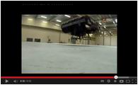
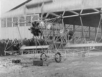
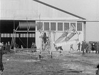
Unknown cyclogyro, supposedly France between 1909 and 1914.
Fragments of "Wings of Fame" movie stores the finals of two unsucceccful tethered tests.
Pay attention to a presence of a tail rotor, in a difference to the majority of other projects.
Les Ailes des Heros - France TV, 2003
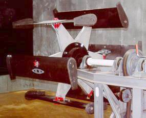
C. Brooks' craft.
According to press messages, C.Brooks from Pattonville (Montana) within more than thirty years was working at creation of the incredible craft with a "paddle-wheel" actuator. Welded framework of a fuselage on style can be referred to middle 1920's. Actuator type is reminiscent of Schroeder's Cyclogyro, however presence of an assembly frame in front of the "paddle wheel" engine allows to assume that thrust had to be produced by one more engine — with the traditional propeller.
"Unconventional Aircraft" by Peter M. Bowers
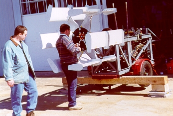
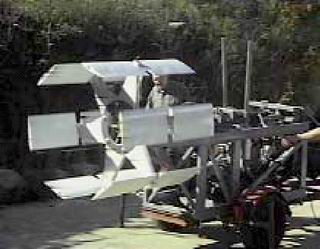
C E Brooks, Pattonville MO. c.1920.
Awkward, Ford-powered creation with what appears to be a short, rotating upper wing, and a side-mounted paddle-wheel arrangement, apparently for forward progress, if any. Little is known about Brooks' apparatus, but judging by a photo showing it in an uncovered state, it didn't exactly look like something that would go tearing down a runway and plunge into the air.
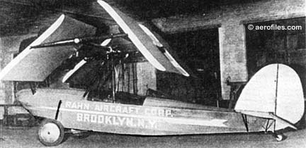
Jonathan Edward Caldwell's Cyclogyro (first project): Santa Monica CA, 1923.
In Feb.1923 he filed an application for a patent covering a rather bizarre aircraft, a "Cyclogyro" that was designed to take off vertically and transition to forward flight. The plane's "wings" were actually small airfoil blades mounted in Ferris wheel-like rotating frames protruding from either side of a conventional aircraft fuselage.
The Cyclogyro patent was granted in the summer of 1927.
In 1924 Swedish engineer Strandgren has received the patent for vertical take-off aircraft. Then he was experimenting with models in France within 9 years and in 1933 has begun construction of full-scale cyclogiro (see below).
In this drawing, surprising are disproportionately small rotors.
This aircraft was constructed in San Francisco about 1930. It was expected that paddle wheel arrangement, named "cycloidal propeller", will create both thrust and lift. The propellers of such a type, where blades are placed in a vertical plane, have appeared effective only for water environment, but hadn't got prevalence for aircrafts.
"Unconventional Aircraft" by Peter M. Bowers
E A Schroeder, 1765 Dolores St, San Francisco CA, 1930.
Cyclogyro (aka S-1) was single-place, open-cockpit plane with Henderson engine. Looked like an ordinary high-wing monoplane, except there were two large paddle-wheels in front instead of a propeller. Possibly the paddle-wheels were able to lift the nose.
Two paddle-wheels of helices and a motorcycle engine reportedly got this contraption going almost 150mph. No other data found, but that alone is impressive, especially if it was in the air!
Haviland Hull Platt, Philadelphia PA, 1933.
Platt Partial plans
Cyclogyro was one-place rotorcraft based on experiments in Germany by Prof Adolf Rohrbach. Paddle-wheel wing arrangement was awarded a US patent (which was only one of many similar patents on file), and underwent extensive wind-tunnel testing at MIT in 1927. In essence, oscillating winglets on this wheel went from positive to negative angles of attack during each revolution to create lift, and their eccentric mounting would in theory produce any combination of horizontal and vertical forces. Still, there is no record of this critter ever flying.
During researches which NACA made with rotor according to Platt's system, was made a sketch of a machine with gross weight of 1360 kg (3000 lbs) and motor power 300 hp, also were calculated rate of vertical climb 210 m/min, and maximal rate of climb with simultaneous forward movement 460 m/min; this last value is about 30% more than what airplane with same power loading can show.
Simplified aerodynamic analysis of the cyclogiro. John B. Wheatley, Langley Memorial Aeronautical Laboratory, Washington, 1933.
A simplified aerodynamic theory of the cyclogiro was developed.
In addition, examples have been calculated: cyclogiro rotor (4 blades, radius: 6 ft., span: 24 ft., chord: 0.472 ft., speed: 300 ftps) and a rotorcraft with two similar rotors (weight: 3000 lb., engine power: 300 hp).
The main conclusions were:
— The cyclogiro is aerodynamically sound in principle.
— Hovering flight, vertical ascent, and reasonable forward speed may be obtained without the excessive expenditure of power.
— Autorotation in a gliding descent is available.
In 1933 Strandgren (see above) has finished a series of experiments with models and together with the company "Liore & Olivier" has begun a construction of full-scale cyclogiro. The most part of charges was paid by Societe d'Expansion Franco-Scandinave.
On the nonvalidated data, in 1934 construction was completed and tests have begun.
Calculated characteristics:
Rotors: diameter — 6 m, five blades, blade length — 245 cm, chord — 40.8 cm, thickness — 3.8 cm. Blades made from duralumin, weight of each — 5 kg. Maximal rotation speed — 180 rpm.
Clerget engine, 130 hp.
Gross weight — about 600 kg.
Rotor's lift — 800 kg at 120 rpm.
The project was well worked. Calculations were checked up in NACA and in DVL (Deutsche Versuchsanstalt fur Luftfahrt, the German Laboratory of Flight), and were recognized as reliable. In 1934 the machine was under construction.
Calculated characteristics:
Total sizes: length — 8.6 m, height — 4.3 m, span — 10 m.
Rotors: diameter — 3.6 m, three blades, blade length — 4.4 m, chord — 0.315 m, maximal rotation speed — 420 rpm.
Engine power — 240 hp, possibly from two motors.
Empty weight — 680 kg, useful load — 270 kg, gross weight — 950 kg.
Speeds: maximal — 200 km/h, travelling (at 75% RPM) — 170 km/h, minimal — 0 km/h, maximal backward — 30 km/h.
Ceiling — 4500 m in forward flight and 500 m in vertical climb.
Range — 400 km with three passengers and 700 km without passengers.
With an overload of 250 kg (that is, with take-off weight 1200 kg) minimal speed — 21 km/h, maximal — 190 km/h, ceiling — 2700 m. Range — 1050 km with two passengers and 1550 km without passengers. Probably, in these cases all overload weight was supposed to be used for extra fuel.
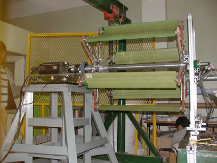
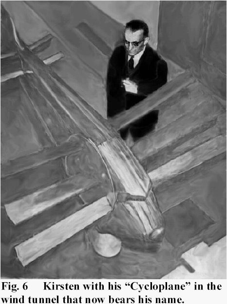
Kirsten's Cycloplane, University of Washington, 1921 — 1934 — 1942.
Cycloidal propeller was patented by prof. Frederick Kurt Kirsten in the beginning of 1920th. The idea was supported by William Boeing. Have begun with a water propeller. Tests of a vessel model have passed successfully, but further business has failed, and Kirsten has sold the patents to Voith-Schneider Corp.
For studying of an air version of a propeller the wind tunnel of the sufficient size was required. Such tunnels were scarce in USA then, and Kirsten has offered the University of Washington to construct their own big (8x12 ft) wind tunnel.
Twist of fate: the tunnel was constructed in 1936, but immediately began to be used so intensively that only in 1942 Kirsten could test a model of his "Cycloplane". Results appeared unfavourable.
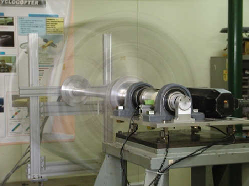
Wind-tunnel tests of a cyclogiro rotor. John B. Wheatley and Ray Windler, Langley Memorial Aeronautical Laboratory, Washington, 1935.
A cyclogiro rotor (4 blades, span and diameter: 8 ft., chord: 0.312 ft.) was tested in the N.A.C.A. 20-foot wind tunnel.
The tests showed that:
— The cyclogiro is capable of vertical ascent, forward flight, and gliding flight without power.
— The probable performance of the cyclogiro is very poor for normal power loadings, and a maximum speed of 100 mph would be attained only with a power loading of less than 7 lb./hp.
— The variations of the power required by the cyclogiro with the vertical and horizontal force coefficients is correctly predicted by mathematical analysis.
— The profile-drag coefficient of the cyclogiro rotor blades increases rapidly with tip-speed ratio and is probably influenced by the blade oscillations.
— Research on the oscillating airfoil is needed in order to clarify past and future rotating-wing research.
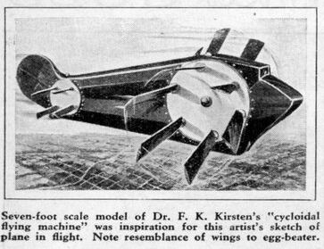
One-seat rotating-wing experiment with 240hp supercharged Wright Whirlwind. Two 6' rotating wings on each side
theoretically would cause the plane to rise or descend vertically, or fly laterally without a conventional propeller up to 100mph, but it is unrecorded if this 15'-long creation ever accomplished any of these feats.
Jonathan Edward Caldwell's Cyclogyro (second project): Washington DC, 1937.
Around 1937 Caldwell revived his 1923 Cyclogyro VTOL concept and started construction on a modified prototype. It was another far-fetched VTOL plane in the style of the impractical flying machines that graced the covers of magazines like Popular Science through the 1930s. The inventor attempted to mount two long three-bladed airfoil-equipped paddlewheels to the sides of a conventional-looking aircraft fuselage, but this time the axles of the paddlewheels ran fore-and-aft, parallel to the length of the machine's body. The airfoils were geared in such a way that as they were spun by the machine's 125hp radial engine, they would theoretically produce enough thrust to lift the craft straight up. One of Caldwell's associates later claimed that this craft actually made successful "test-hops" to a height of about six feet.
The original project of the VTOL passenger craft was offered by German inventor Reinhold Kalletsh. During parking on ground this machine will look like a wingless plane, basing on five-meter telescopic undercarriage legs. Feature of this craft is the elevating arrangement consisting of three rotating in perpendicular to fuselage plane bars-spokes with elliptic, attached with a hinges, blades-wings on its ends. On takeoff and at landing such a "propeller", made of wings, will be set in rotation with the use of jet nozzles, supplied with gases from turbojet engines of the craft. The similar arrangement, but smaller in size, will be established on a fuselage tail. During rotation of "propellers" the special device will pivot the blades-wings so that it will always be under some angle of attack to the airflow and, hence, will create necessary elevating force. After the vertical takeoff unusual "propellers" will stop and its blades-wings will begin to carry out its traditional wing functions.
"Nauka i Zhizn" («Siience and Life») 9/1966
Rotary device driven by a moving fluid. Charles Andre Sicard, French patent 75.01907, 1975; US patent 4048947, 1976—1977.
It isn't an aircraft. It's a wind turbine only.
But it's a cyclogiro.
And I have found it worth of attention for a combination of simplicity and efficiency — "cheap and tough".
A rotor consists of two parts only — of a shaft with arms and of a set of blades. Variation of an angle of incidence is "automatic". The blades of a symmetric airfoil, freely rotatable around the leading edge, are supplied with counterweights to place the centre of gravity into the necessary point. When the wind blows, the interaction of the aerodynamic and centrifugal forces provides a correct "cyclogyro style" orientation of blades during rotation.
Maybe, springs would be better instead of counterweights (thus speed of rotation of a rotor would be less dependent upon speed of a wind). But, probably, this version was already patented by somebody else.
Besides, for increase of efficiency the blades can be made floppy. Then under a pressure of a wind its airfoil will become asymmetrical, curved in the necessary side.
It's a pity that such a graceful decisions are not suitable for the aircraft.
Lift augmenting device for aircraft. Thomas H. Sharpe, US patent 4194707, 1977—1980.
Cyclogiro rotors of small radius, covered with casings, are placed in a wing and used as ordinary fans. Angles of incidence are controlled by simplified eccentric mechanism. In horizontal flight the rotors are disconnected from the engine, and horizontal thrust is created by usual variable-pitch pushing propeller. The longitudinal balancing is provided by an elevator placed in an airflow from propeller. The elevator has an additional shutter for thrust reversind.
The second version of the device is intended for high-speed aircrafts. Turbojet engines and two pairs of air intakes (top and lateral) are used. Transmission from the engines to cyclogiro rotors is hydraulic. In horizontal flight top air intakes and fan outlets are closed with shutters. The additional control facilites for a hovering flight — jet nozzles on the wings and on the vertical stabilizer, supplied with compressed air from turbojet compressors — are stipulated.
In all the rest this variant is similar to previous.
Neither in the first variant, nor in the second the main cyclogiro advantage — a possibility to redirect thrust vector instantly within 360° — is not used.
Propulsive lifting rotors. Marcel Chabonat, French patent 76.39820, 1976; US patent 4210299, 1977—1980.
The project is delightful in its own way.
The rotors are two-bladed.
In the first version, the variation of an angle of incidence is "automatic" — the blades are freely swinging between the terminators under the action of aerodynamic and/or centrifugal forces. When moving down, the blade produces lift, when moving up — thrust. Thus, in the bottom of a cycle the angle of incidence changes abruptly, with an impact. Therefore terminators, on a plan of the inventor, should be elastic.
In the second version the angle of incidence is changing "by program" with the means of profiled cams. It is supposed to have a set of cams for different modes of flight (take-off, climb, cruise flight, descent or landing). The style of this mechanics reminds the tape drive mechanism of the tape recorder of 1960's. Though the toothed belts are used instead of elastic ones.
And one more detail: it is supposed to place the elevator assembly (at the presence of those) in front of fuselage, to prevent its appearance in the airflow from the rotor.
Cyclorotor composite aircraft. Arthur G. Crimmins, US patent 4482110, 1980—1984.
The main purpose of this composite aircraft is to be a flying crane. The body weight of the craft is counterbalanced by aerostatic lift of a balloon 1, and weight of a cargo — by lift of cyclogiro wings 2.
The wings and thrust means are mounted on turnable pylones 3, playing also a role of the propeller blades. The device can accept a configuration of a "classical" dirigible, "classical" cyclogiro and all intermediate. Due to this there are no restrictions on a summary thrust vector orientation — that is what the flying crane needs for.
The large, typical for balloons, size of this craft will allow to spin it up to significant tip speed while the moderate centrifugal stresses.
Paddle wheel rotorcraft. Heinz A. Gerhardt, US patent 5265827, 1992—1993.
Aerodynamically it's a usual cyclogiro.The longitudinal balancing is provided either by vertical propeller on a vertical stabilizer, or by second pair of cyclogiro rotors.
Feature of this craft is absence of kinematic management of an angle of incidence of blades. Instead, on each blade the hydrocylinder constantly controlled by the computer on the chosen law is established. This way it is supposed to achieve an optimum performance of each blade at all regimes of flight.
This site was out of updates for six years. Now it's a time to continue.
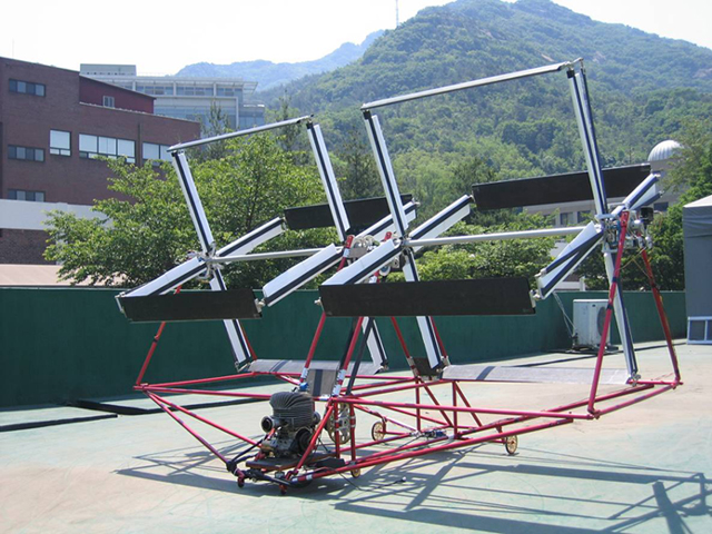
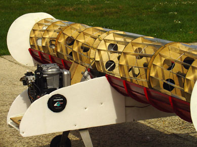
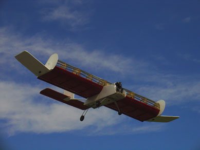
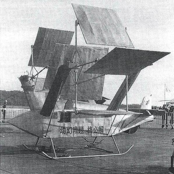
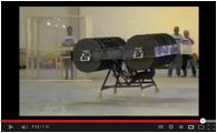
«Holly Eagl» aircraft designed by Dousan Chzhang
The most unusual exhibit - «flapping-wing helicopter» - was presented by ordinary Chaoyang resident, 46-year Dousan Chzhang. Exotically looking, this device drew attention of both experts and simple visitors, and the designer was bombarded
with questions. The designer have studied birds' flight for a long time, and for creation of the aircraft called «Holly
Eagl», two years were spent. The author also took out the patent for his creation. Besides, Dousan Chzhang showed two more
his-own-hand-made aircrafts: a helicopter and «Dou-Quiang III» plane.
Sergey Mikhaylov, «AIRSHOW CHINA 2002» («Aviatsia i Kosmonavtika» («Aviation and Astronautics») 01.2003)
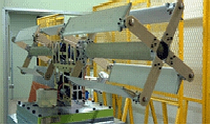
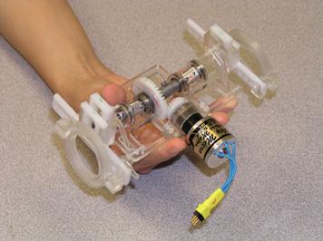
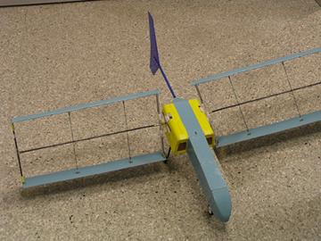
Aircraft. Meinhard Schwaiger, USA patent № 7735773, 2010.
As a whole: it's a classical cyclogyro with longitudinal rotors.
Design feature: cyclic control not only for attack angle, but also for blade curvature is provided.
The second feature: original (and doubtful) autorotation mode was suggested.


 Propulsive lifting rotors. Marcel Chabonat, French patent 76.39820, 1976; US patent 4210299, 1977—1980.